Finite element analysis
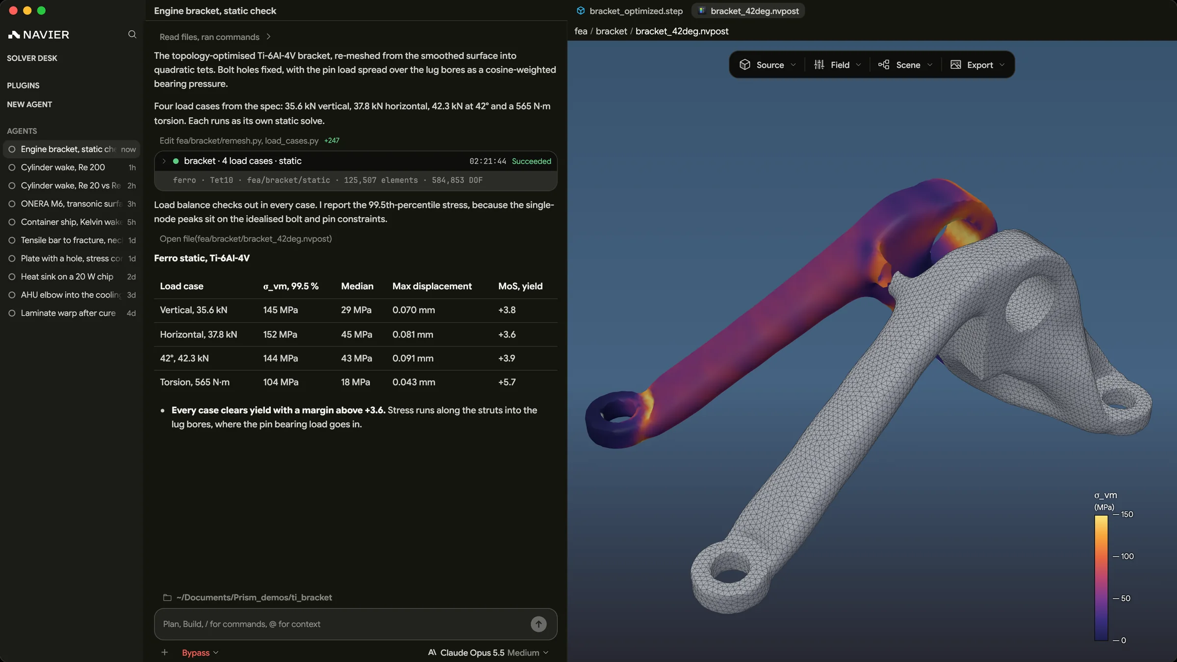
Finite element analysis, or FEA, predicts how a part deforms and where it is stressed under load. It splits the part into many small elements, approximates the displacement inside each one, and assembles them into one large set of equations.
The finite element method is the mathematics. FEA is its use on an engineering problem. The same method also solves heat conduction, electromagnetics and other field problems.
The core equation
For a linear static analysis, every element adds a stiffness matrix, and the assembled system is
holds the unknown displacements at the nodes, the applied loads, and the stiffness of the whole part. Solve for the displacements, and the strains and stresses follow from them.
The steps
- Geometry, simplified where detail doesn't matter.
- Mesh, finer where stress changes quickly.
- Material, at least Young's modulus and Poisson's ratio.
- Loads and supports, meaning forces, pressures, temperatures and how the part is held.
- Solve.
- Check the deformed shape, the reaction forces and the stresses against allowables.
A worked example
A steel bar is 1 m long with a 100 mm² cross-section and = 200 GPa. It is fixed at one end with 10 kN pulling on the other. Split it into two elements of 0.5 m, and each behaves like a spring.
With the fixed node removed, the two free nodes give
so = 0.25 mm and = 0.50 mm. The hand formula gives the same 0.50 mm, and the stress is 100 MPa. Real models work the same way, with millions of unknowns instead of two.
Element types
| Element | Use it for |
|---|---|
| Beam | Frames and long, slender members |
| Shell | Thin walls such as sheet metal, panels and composite laminates |
| Tetrahedron | Complex 3D shapes. Use 10-node tets, since 4-node ones are too stiff |
| Hexahedron | Regular 3D shapes, with better accuracy per node |
Beyond static stress, FEA covers natural frequencies, buckling, heat, vibration over time, and nonlinear problems such as plasticity and contact.
Where it matters
- Before hardware exists. Weak spots show up before a part is made or tested.
- Lighter parts. Stress plots show where material can come off.
- Design choices. Several variants can be compared under the same loads.
Common mistakes
- Trusting a stress singularity. At a sharp inside corner or a point load, stress keeps rising as the mesh gets finer. Model the real fillet, or judge the result away from it.
- Skipping the mesh check. Refine where it matters and confirm the result stops changing.
- Over-constraining. Fixing a face that is really bolted makes the part too stiff and moves the stress.
- Mixing units. Most solvers have none, so millimetres with pascals is off by a million.
- Reading a linear result above yield as a real stress. See the stress–strain curve.
Finite element analysis using Navier AI
Prism runs structural FEA on Ferro, its built-in solver, and installs CalculiX, code_aster and Elmer from inside the app. Describe the part, its loads and its supports. The agent builds the geometry and the model, runs it on your machine and reports back. You can turn on approval before each step, and every input file is yours to open.
The agent can also run design variants and compare them. Our composite layup study runs four carbon/epoxy layups on the same bolted plate in CalculiX, in 20 solves and 86 seconds of solver time. Download Prism to run your own.
References
- R. D. Cook, D. S. Malkus, M. E. Plesha and R. J. Witt, Concepts and Applications of Finite Element Analysis, Wiley.
- K.-J. Bathe, Finite Element Procedures, Prentice Hall.