Which carbon-fibre layup survives the load?
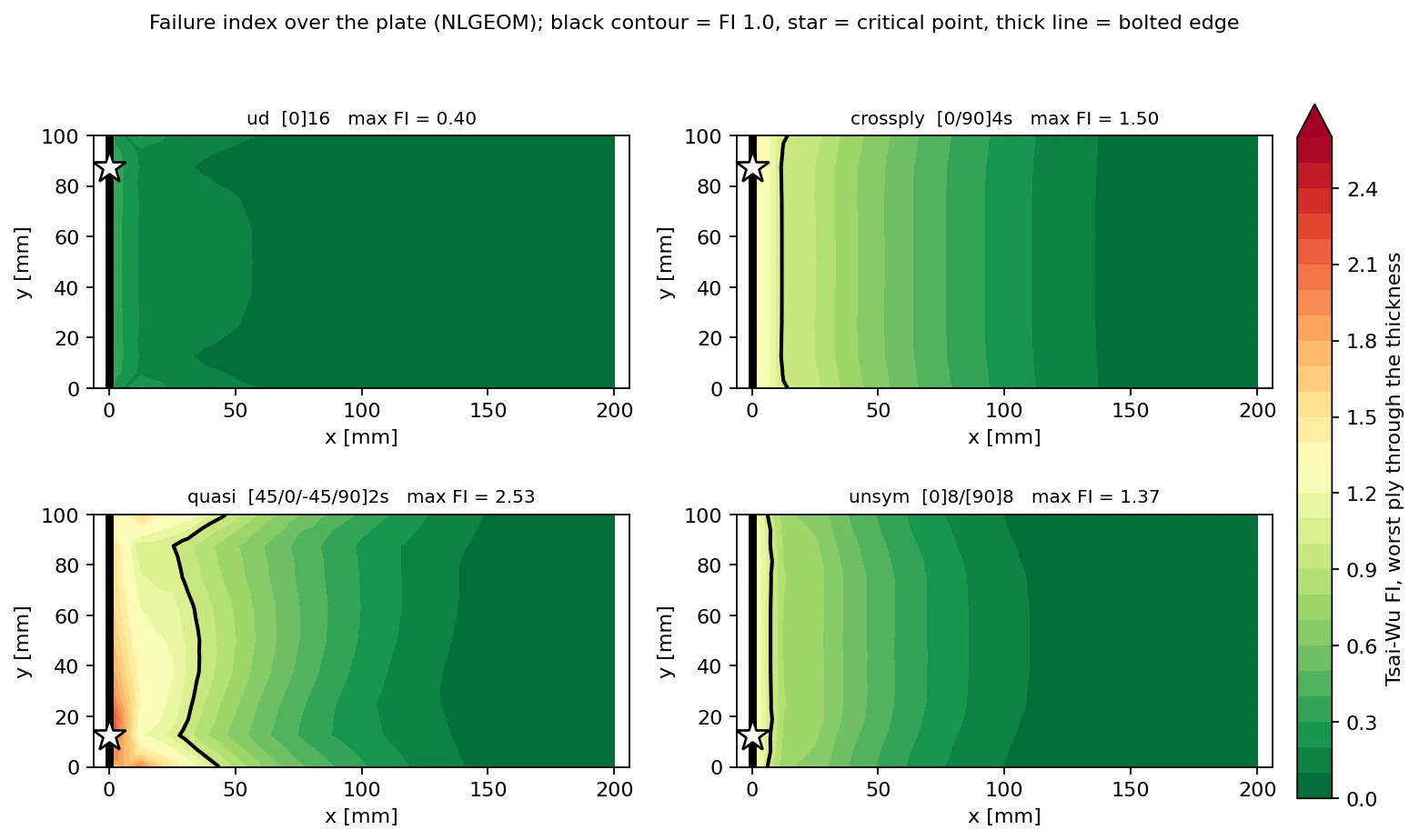
Same plies, same mass, same plate: only the stacking order changes. Under 0.02 MPa only the unidirectional stack passes. The quasi-isotropic stack, the usual safe default, is the first to fail. In all four it is the matrix that cracks, at the bolted edge, while the fibres never reach 90% of their strength.
+0.87
MARGIN · [0]₁₆, THE ONLY PASS
10.1 KPA
QUASI-ISOTROPIC FAILS FIRST
180%
PEAK TRANSVERSE STRESS / Yₜ
20
SOLVES · 86 S IN TOTAL
THE PROBLEM
The plies are fixed. Only their order is up for decision.
A flat carbon/epoxy plate is bolted along one edge and loaded by a uniform pressure over its face. Sixteen plies, 2 mm of laminate, one material. The four candidate stacks share the mesh, the mass and the ply properties, so any difference in the results is the layup and nothing else.
Each composite shell is expanded into a stack of sixteen quadratic bricks, one per ply, so stress and strain are resolved inside every individual ply rather than smeared through the thickness. Failure is then judged in each ply's own fibre axes, at every node, by three criteria: maximum stress, Tsai-Hill and Tsai-Wu. Tsai-Wu carries the headline margins.
| Plate | 200 × 100 × 2.000 mm | left edge bolted, three edges free |
| Plies | 16 × 0.125 mm | carbon/epoxy, T300/914 class |
| Mass | 3.16 kg/m² | identical for all four layups |
| Load | 0.02 MPa, uniform | 400 N over the face, normal to it |
| Cure | 453 K → 293 K | stress-free at cure, 160 K cool-down |
| Model | 128 S8R composite shells | expanded to 2,048 C3D20R ply bricks |
| Case | Stacking sequence · bottom to top | Symmetric | Balanced |
|---|---|---|---|
| ud | [0]₁₆ | yes | yes |
| crossply | [0/90]₄ₛ | yes | yes |
| quasi | [45/0/−45/90]₂ₛ | yes | yes |
| unsym | [0]₈[90]₈ | no | yes |
The supplied model carries stiffness but no strength, so the five ply allowables a failure criterion needs were added from the standard published set for this class of material. They are an assumption, and the conclusion rests on one of them in particular: Yₜ, the tensile strength across the fibres.
| Fibre tension · MPa | Fibre compression · MPa | Transverse tension · MPa | Transverse compression · MPa | In-plane shear · MPa |
|---|---|---|---|---|
| 1500 | 1200 | 50 | 250 | 70 |
STIFFNESS
In-plane isotropy is the wrong thing to buy for bending.
Bending along the plate is resisted by the plies furthest from the mid-plane. [0]₁₆ puts fibres there and is the stiffest. The quasi-isotropic stack puts ±45° plies on both surfaces and deflects 2.1× further. The unsymmetric stack is worst at 3.5×, because its extension–bending coupling lets the bending moment stretch the laminate as well, a compliance no symmetric stack has.
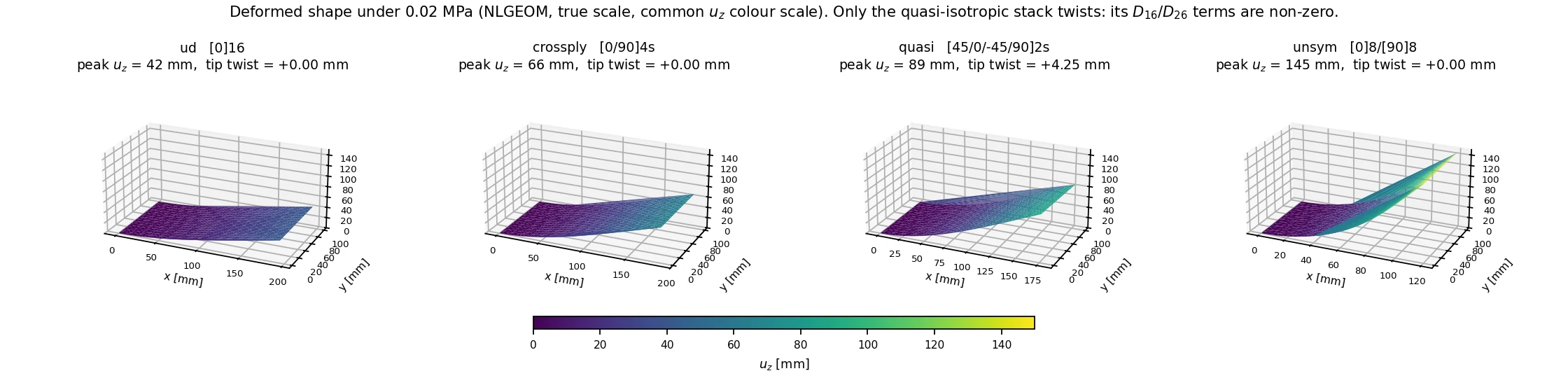
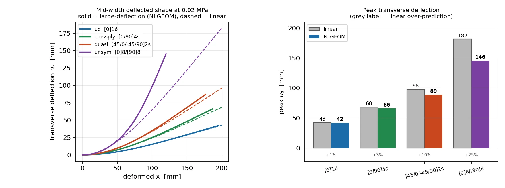
The deflections are large enough that a linear solution is no longer the answer. It over-predicts by 1% for [0]₁₆ and by 25% for the unsymmetric stack, which rotates far enough that the pressure stops acting on its original moment arm.
Every margin below therefore comes from the geometrically nonlinear solution. The linear one is kept as a comparison, and the comparison turns out to matter less for stress than for shape: the root moment is fixed by statics, so the peak ply stress at the bolted edge moves by under 2% in the symmetric stacks.
| Layup | Tip deflection · linear, mm | Tip deflection · nonlinear, mm | Linear over-predicts | Tip twist · mm | Deflection / thickness |
|---|---|---|---|---|---|
| [0]₁₆ | 42.7 | 42.1 | +1% | 0.00 | 21 |
| [0/90]₄ₛ | 68.4 | 66.2 | +3% | 0.00 | 33 |
| [45/0/−45/90]₂ₛ | 96.1 | 86.9 | +11% | 4.25 | 43 |
| [0]₈[90]₈ | 181.8 | 145.3 | +25% | 0.00 | 73 |
PLY BY PLY
The fibres are fine. The matrix runs out.
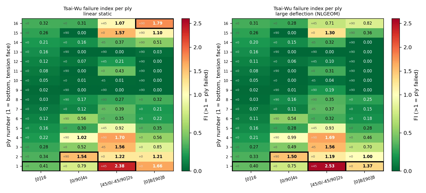
The largest fibre stress anywhere is 1,302 MPa in the quasi-isotropic stack, 87% of Xₜ. The transverse stress reaches 90 MPa, 180% of Yₜ. Carbon/epoxy is about thirty times stronger along the fibre than across it, so unless a laminate is designed to keep transverse stress out of its plies, the matrix fails first.
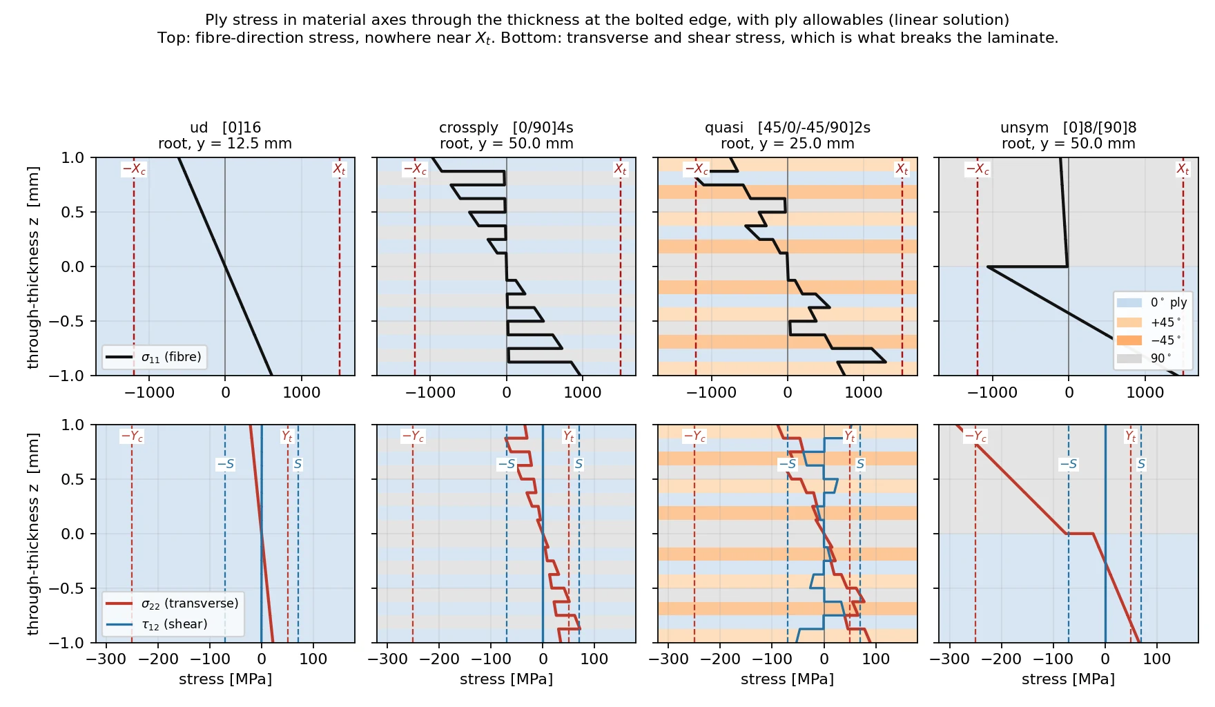
Two sources of transverse tension, both set by the layup
A 90° ply between 0° plies is forced to follow their axial strain, which puts it into tension across its own fibres. That is why the cross-ply's critical ply is a 90° ply carrying 70 MPa of transverse stress and almost no fibre stress at all.

The bolted edge adds the rest. It holds the plate's width while the plate tries to contract under axial tension, and the restraint becomes transverse tension directly. Every critical point in the study lies on that edge, in an outer ply on the tension face.
| Layup | Critical ply | Fibre stress · MPa | Transverse stress · MPa | Shear stress · MPa | Mode |
|---|---|---|---|---|---|
| [0]₁₆ | 1 · 0° | 614 | 21.4 | 0.9 | matrix tension |
| [0/90]₄ₛ | 2 · 90° | 27 | 70.2 | −0.3 | matrix tension |
| [45/0/−45/90]₂ₛ | 1 · +45° | 712 | 89.8 | −59.1 | matrix tension |
| [0]₈[90]₈ | 1 · 0° | 1268 | 56.6 | −7.0 | matrix tension |
MARGINS
Three criteria, one ranking, one survivor.
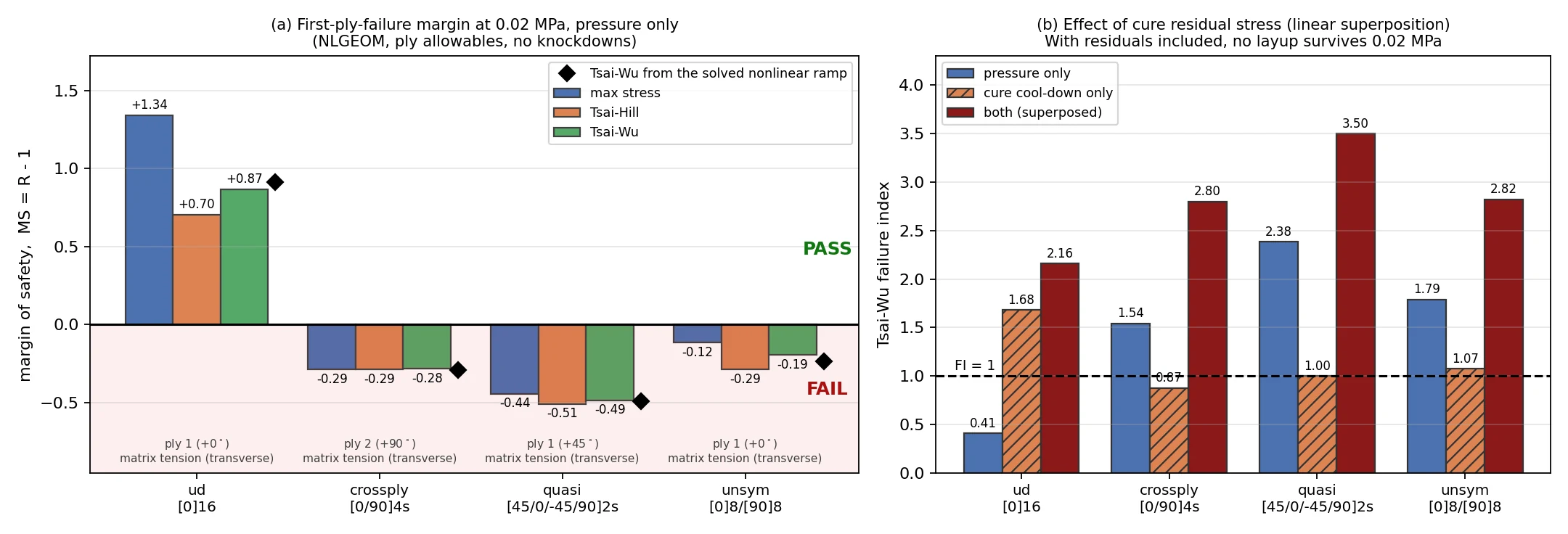
The criteria agree on the order and on the mode, and differ only in magnitude. The largest gap is for [0]₁₆: maximum stress gives a margin of +1.34, Tsai-Wu +0.87, because Tsai-Wu accounts for 614 MPa of fibre tension and 21 MPa of transverse tension acting in the same ply. Quoting the least favourable criterion in every case changes no verdict.
The quasi-isotropic stack is the worst performer, not the safe one. It has the lowest bending stiffness, and it puts a +45° ply on the most strained surface, where that ply picks up transverse tension and 59 MPa of in-plane shear against an allowable of 70.
| Layup | FI · Tsai-Wu | MS · max stress | MS · Tsai-Hill | MS · Tsai-Wu | First-ply failure · kPa | At 20 kPa |
|---|---|---|---|---|---|---|
| [0]₁₆ | 0.40 | +1.34 | +0.70 | +0.87 | 38.2 | pass |
| [0/90]₄ₛ | 1.50 | −0.29 | −0.29 | −0.28 | 14.2 | fail |
| [45/0/−45/90]₂ₛ | 2.53 | −0.44 | −0.51 | −0.49 | 10.1 | fail |
| [0]₈[90]₈ | 1.37 | −0.12 | −0.29 | −0.19 | 15.3 | fail |
SOLVED, NOT SCALED
The failure pressure, read off the solution.
Once the plate deflects, stress grows more slowly than pressure, so a failure pressure cannot honestly be found by scaling one solution. Each layup was re-run with the pressure ramped past its own failure point, and first-ply failure read where the solved failure index crosses 1.
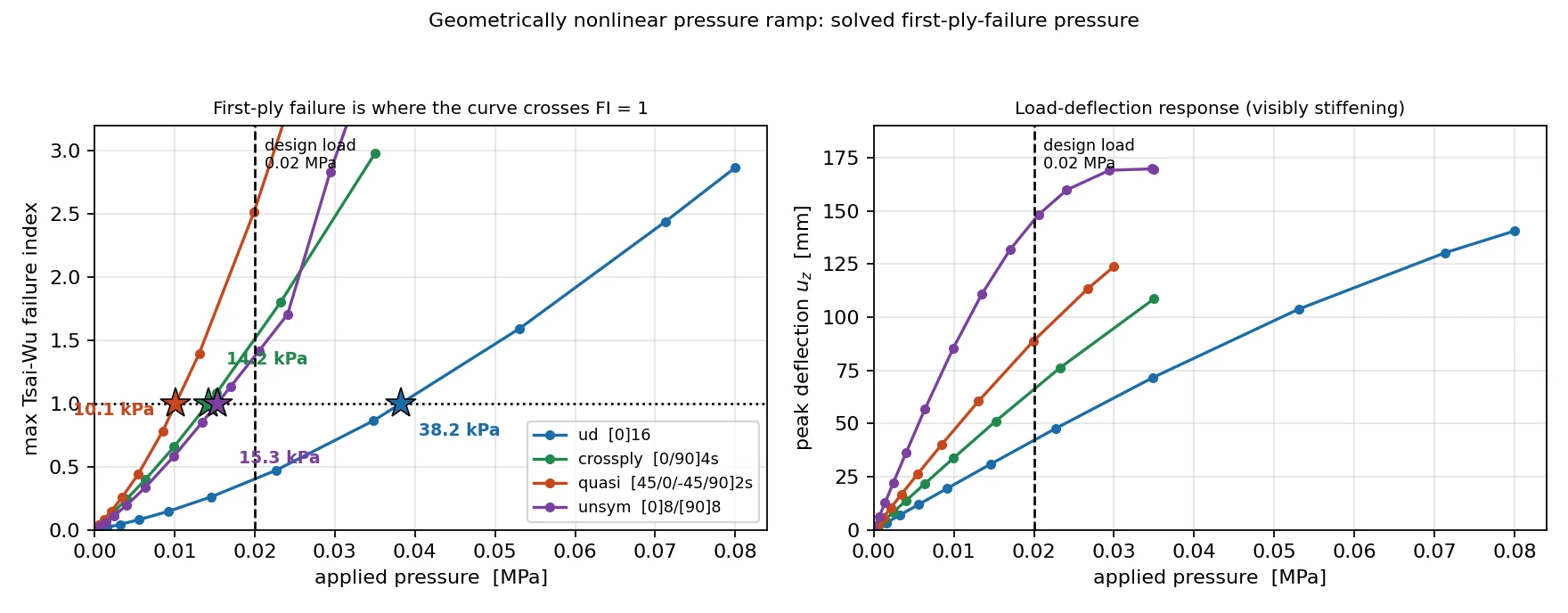

[0]₁₆ reaches first-ply failure at 38.2 kPa, 1.91× the design pressure. The unsymmetric stack fails at 15.3 kPa, the cross-ply at 14.2 and the quasi-isotropic stack at 10.1, half the design load and 3.8× lower than [0]₁₆.
As margins, the ramp gives +0.91, −0.23, −0.29 and −0.49, each within 0.05 of the margin from scaling the single design-load solution. The response is distinctly nonlinear, but the scaled strength ratio holds up here, and now that is checked rather than assumed.
CURE RESIDUAL STRESS
Most of the budget is spent before any load arrives.

A laminate is stress-free at its cure temperature, not at room temperature. On cooling, a ply contracts across its fibres by 28 × 10⁻⁶ per kelvin and barely moves along them, so a 0° ply and a 90° ply bonded together fight each other. The 160 K cool-down from cure leaves every ply of the cross-ply and quasi-isotropic stacks with 40.6 MPa of transverse tension away from the edge. That is 81% of Yₜ, consumed by the layup itself.
Superpose the cure state on the pressure case and no layup passes. [0]₁₆ carries almost no ply-to-ply residual stress in the far field, but at the bolted edge the restraint gives it its own, and it reaches a failure index of 2.16. The cool-down also disqualifies the unsymmetric stack outright: with no load at all it bows 11.1 mm out of plane from its extension–bending coupling, while the symmetric stacks stay flat to 0.01 mm.
| Layup | Warpage · mm | FI · pressure | FI · cure | FI · both | MS · both |
|---|---|---|---|---|---|
| [0]₁₆ | 0.01 | 0.41 | 1.68 | 2.16 | −0.39 |
| [0/90]₄ₛ | 0.01 | 1.54 | 0.87 | 2.80 | −0.55 |
| [45/0/−45/90]₂ₛ | 0.01 | 2.38 | 1.00 | 3.50 | −0.61 |
| [0]₈[90]₈ | 11.12 | 1.79 | 1.07 | 2.82 | −0.54 |
VERIFICATION
A peak on a constraint is a question, not an answer.
Every critical point sits exactly on the bolted edge, which always raises the question of a constraint singularity. Over a 3× in-plane refinement the critical failure index moves by 1.0% at most and tip deflection by under 0.3%. The peak is a converged, physical stress, not an artefact of the mesh.
| Layup | FI · 2,048 el. | FI · 8,192 el. | FI · 18,432 el. | Spread |
|---|---|---|---|---|
| [0]₁₆ | 0.406 | 0.404 | 0.404 | 0.6% |
| [0/90]₄ₛ | 1.540 | 1.541 | 1.541 | 0.1% |
| [45/0/−45/90]₂ₛ | 2.385 | 2.398 | 2.409 | 1.0% |
| [0]₈[90]₈ | 1.790 | 1.788 | 1.784 | 0.3% |
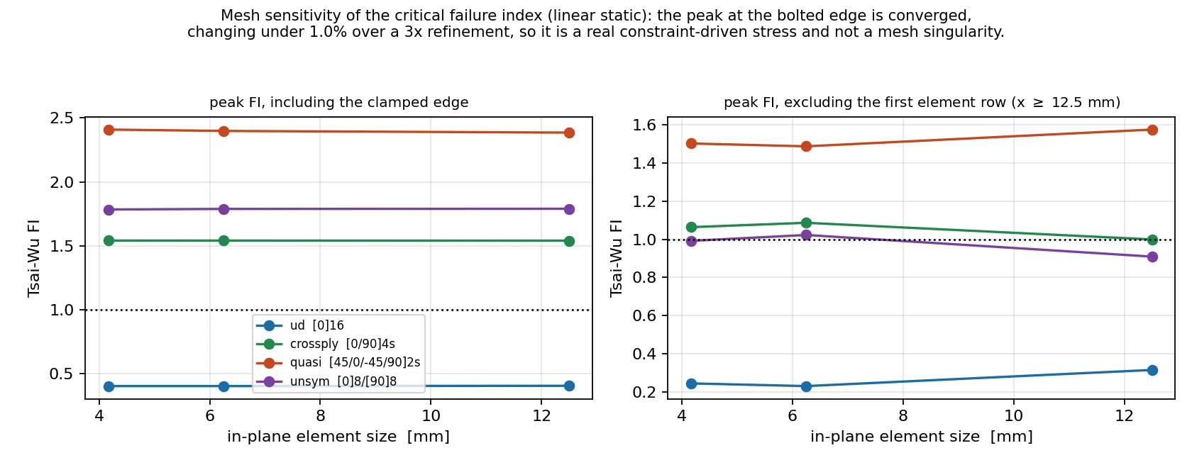
Ply-level stress in a rotated material frame is easy to get silently wrong, so the extraction chain was checked as well. At every node the stress rotated into ply axes was compared with the ply stiffness acting on the strain rotated the same way. The worst relative error over all four linear models is 4 × 10⁻⁶, which confirms the frame, the ply-angle mapping and the sense of the rotation in one test.
Statics closes too. Integrating bending stress over the bolted section recovers 99.9% of the 40,000 N·mm root moment the load requires, for every layup.
RECOMMENDATION
[0]₁₆ wins the study. It should not be the part.
[0]₁₆ is best on every measure here: stiffest, lowest failure index, highest failure pressure, no twist and no warpage. But it wins only because the load is pure bending in one direction. A pure unidirectional laminate has no shear capability and no damage tolerance across the fibres. A 0°-dominated stack with some off-axis plies, such as [0/0/0/45/0/−45/0/90]ₛ, keeps most of the bending stiffness and buys those back.
The larger finding is that the plate is under-designed for this pressure whatever the order. Bending stress goes as one over thickness squared, so reaching a failure index of 1 needs about 2.4 mm for the cross-ply and 2.8 mm for the quasi-isotropic stack before cure stress or any factor of safety. And even the best stack deflects 42 mm, 21% of its span. A stiffness requirement will size this part before strength does. The right next step is to set that requirement and a joint model, then size thickness and layup together.
LIMITATIONS
Stated rather than buried.
The strength allowables are assumed: standard published values for this class of ply, not coupon data. Every margin scales with them, and Yₜ = 50 MPa alone decides the outcome.
No knockdowns and no factor of safety. Under a 1.5 factor and a 0.8 hot/wet knockdown, the winning layup falls just short as well.
The bolted edge is idealised as fully built-in. Every critical point lands on it, so the joint model is the largest single uncertainty in the strength result.
First-ply failure only. No progressive damage and no delamination check, although interlaminar stress reaches 17 to 114 MPa at the bolted edge in the nonlinear runs.
Cure and pressure are combined by linear superposition. A combined nonlinear case was not run.
BRING US THE DECISION
Before the layup is frozen.
If a stack is being chosen on habit, or a margin rests on a laminate-level number nobody has taken down to the ply, send us the geometry, the loads and the candidate layups. Whichever ply fails first, and why, is cheaper to find before the tooling is cut.
CalculiX 2.23, run through Prism's solver daemon in a containerised runtime: 20 solves, 86 s of solver time in total. 16 × 8 S8R composite shells, expanded by CalculiX to 2,048 C3D20R ply bricks and 16,304 nodes; root edge fixed in all six degrees of freedom. Linear static and geometrically nonlinear in 7 to 13 increments, a nonlinear ramp past first-ply failure, and a mesh study to 48 × 24. Ply stress rotated to material axes per node, with the material rotation removed by polar decomposition in the nonlinear runs. Tsai-Wu with F₁₂ = −0.5√(F₁₁F₂₂). Ply stiffness as supplied; strength allowables assumed. Basis: a representative plate, not a named client.