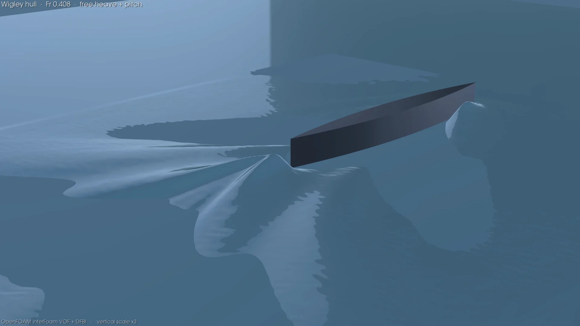
Sinkage within 1.03 mm, across five speeds.
The 3 m Wigley hull, free to heave and pitch, run at five speeds against the 1983 cooperative towing-tank measurements. Every sinkage result lands inside 1.03 mm, and total resistance carries a ±2.10% numerical uncertainty on a converged grid family.
≤1.03 MM
SINKAGE ERROR · FIVE SPEEDS
±2.10%
CT NUMERICAL UNCERTAINTY
5
FROUDE NUMBERS
4.34 M
CELLS
THE BENCHMARK
A hull where a systematic error has nowhere to hide.
The Wigley hull earns its place because its geometry is analytic — there is no offset table to get wrong — and the published measurements span a speed sweep rather than a single point. Run five speeds instead of one and a systematic error has to show itself somewhere across the curve. One did.
OpenFOAM v2412: interFoam with a VOF free surface and dynamic body motion, k-epsilon with a turbulent-viscosity limiter. Half-domain, 4.34 million cells, three hull lengths to the side boundary, 10 L/U per speed. Heave and pitch are free; the other four rigid-body motions are restrained. One detail matters more than any of these, and it is the subject of a later section: a cell face is aligned on the waterline.
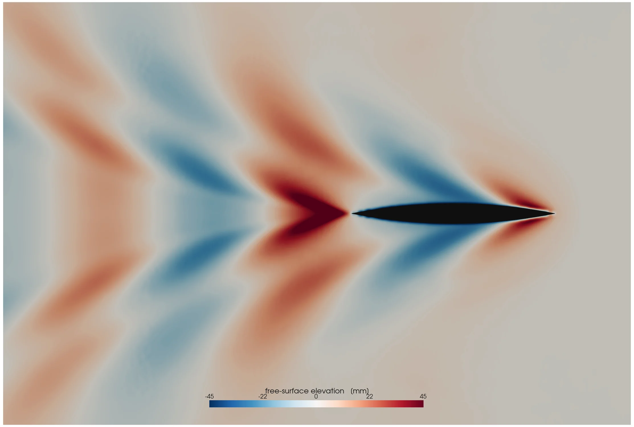
Free-surface elevation at Fr 0.408 — the transverse and diverging components of the Kelvin wake.
SINKAGE · VS TOWING TANK
Within 1.03 mm at every speed.
The worst point is the slowest speed, where sinkage itself is only 2.70 mm; at Fr 0.316 the difference is 0.09 mm. Computed trim changes sign between Fr 0.250 and Fr 0.316 and grows bow-down from there. Skin friction stays close to the ITTC line, with Cv/Cf between 0.99 and 1.07.
| Froude number | Simulation · mm | Experiment · mm | Difference · mm |
|---|---|---|---|
| 0.177 | 1.67 | 2.70 | 1.03 |
| 0.250 | 4.12 | 4.80 | 0.68 |
| 0.316 | 7.41 | 7.50 | 0.09 |
| 0.374 | 11.49 | 12.00 | 0.51 |
| 0.408 | 14.34 | 15.00 | 0.66 |
WHERE THE FIRST ANSWER WENT WRONG
The shape of the error is what gave it away.
Sinkage varied 5.6 times across the speed range while the error stayed near-constant at +6.59 ± 0.80 mm. An offset that does not scale with the quantity it corrupts is a measurement-datum problem, not a physics failure — so the fix is a mesh decision, not a turbulence-model knob.
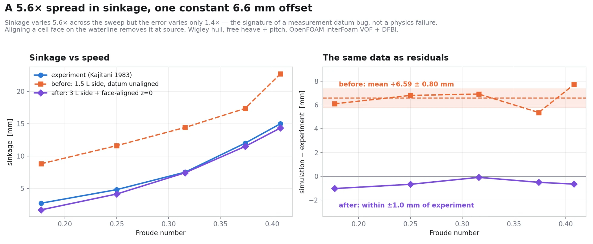
Fixed at source. Nothing tuned toward the curve.
Aligning a cell face on z = 0 and widening the side clearance to three hull lengths removed the offset where it originated, rather than subtracting it afterwards. Nothing in this study is corrected, offset, or tuned toward the experimental curve. That distinction is the whole reason the sinkage agreement above is worth anything.
TOTAL RESISTANCE · THE UNCERTAINTY BUDGET
A resistance number that has stopped moving.
At Fr 0.316 the total-resistance coefficient is Ct = 5.638 × 10⁻³ with a combined numerical uncertainty of 2.10%. It has stopped moving with grid, time step and iteration, and it carries a stated band, so the figure can be quoted with its error bar rather than as a bare number.
GRID
0.77%
GCI on the fine grid, observed order p = 1.635
ITERATIVE
1.70%
Ct peak-to-peak over the mean, trailing 25%
TIME STEP
0.95%
Ct shift when the max Courant number is halved
COMBINED
2.10%
root-sum-square of the three components
Fr 0.316 — free surface, rigid-body motion, and the pressure and viscous resistance coefficients. The iterative uncertainty is the peak-to-peak scatter over the trailing quarter of these traces.
THE GRID FAMILY
Three grid studies failed before one worked. None failed on physics.
Refining everything at once let the mesher reach a different prism-layer coverage on each member — 75, 88 and 91% — so the near-wall treatment changed along with the grid, and Cv/Cf drifted from 1.009 to 1.159. A grid study whose members do not share a wall model is not measuring discretisation error.
Holding the hull-adjacent cell at 12.5 mm and coarsening only the bulk restored geometric similarity. Ct then moved 1.4% across a 14× cell-count range, at an observed order of 1.635.
| Grid | Cells | Layer coverage · % | Ct × 10³ | Cv/Cf |
|---|---|---|---|---|
| Coarse | 305,468 | 88.0 | 5.558 | 1.015 |
| Medium | 711,709 | 90.9 | 5.579 | 0.997 |
| Finest | 4,338,220 | 88.1 | 5.638 | 1.009 |
THE WAVE TANK ITSELF
Check the instrument before you trust the reading.
Before the hull results mean anything, the tank gets checked on its own: a two-dimensional Stokes II case with no hull in the domain. Wavelength lands within 1.79% of linear theory and wave height within 2.30%. This says nothing about the hull. It says the waves arriving at the hull are the waves we asked for.
One feature is still unexplained. Wave-height modulation grows from 10.4% to roughly 21% with distance down the tank. The obvious suspect is outlet reflection, but porous beaches of two and three wavelengths each moved it by less than a point — so that explanation is not established, and we are not claiming it.
SCOPE
What the study covers, and what it leaves out.
Sinkage is validated against the 1983 cooperative towing-tank measurements at all five speeds. Total resistance is reported with its numerical uncertainty from the grid, time-step and iterative studies, and the skin-friction component stays within 7% of the ITTC line at every speed.
The domain sizing, the waterline-aligned mesh and the single near-wall setting were chosen for this hull at these speeds. Everything listed as outside this study is beyond what it establishes.
SUPPORTED BY THIS STUDY
- Sinkage at five Froude numbers
- Computed trim trend and sign reversal
- Skin-friction ratio, Cv/Cf
- Numerical uncertainty on Ct, ±2.10%
- Grid convergence across the mesh family
- Wave generation and propagation
OUTSIDE THIS STUDY
- Trim against measurement
- Far-field wave-tank modulation
- Seakeeping or RAOs
- A second mesh family or near-wall setting
BRING US THE HARD CASE
Free surface, moving bodies, or a number someone has to defend.
Send the geometry, the operating conditions and whatever reference data exists. An engineer will tell you what can be tested, what evidence it will take, and what the comparison will not be able to prove.
OpenFOAM v2412, interFoam VOF with DFBI rigid-body motion, k-epsilon with a turbulent-viscosity limiter. L = 3 m Wigley hull (B/L 0.1, T/L 0.0625, Cb = 4/9), free in heave and pitch, restrained in surge, sway, roll and yaw. Half-domain, 4,338,220 cells, three hull lengths of side clearance, 10 L/U per point, a cell face aligned on z = 0. Scatter is quoted peak-to-peak over the trailing 25%. Experimental reference: the 1983 cooperative towing-tank programme, sinkage. Ct is reported with its combined numerical uncertainty from the grid, iterative and time-step studies.