What decides whether a storage tank actually mixes.
A transient, buoyancy-driven simulation of jet mixing in a stratified 246,727-gallon potable water tank, across five inlet configurations run concurrently on one workstation. Destratification is set by the momentum flux the inlet manifold delivers, not by flow rate and not by Froude number.
2.7×
MORE DESTRATIFICATION · SAME FLOW
1.6%
APART ON A CONTROLLED MESH
5
CASES CONCURRENT ON ONE BOX
2.8 H
WALL CLOCK, ALL FIVE
THE FINDING
It orders on jet momentum flux, and the matrix was built to give that answer a chance to lose.
The case matrix was organised on the densimetric Froude number, Fr = U/√(g′d), deliberately, because it gives a velocity-holding port a chance to fail. It didn't. What the destratification rate orders on is jet momentum flux, Q·U.
This is not a new result and is not presented as one. Rossman and Grayman established from scale-model experiments in 1999 that tank mixing time during fill scales as V²ᐟ³/M¹ᐟ², with M = Q·U, and it is the basis variable-orifice inlets are designed on. What this study adds is an independent reproduction of that structure from first principles, by a model with no stake in the answer.
| Tank | 40 ft × 26 ft SWD | 246,727 gallons, potable water |
| Stratification | 5 K | thermocline at 55% of depth |
| Solver | OpenFOAM v2412 | buoyantBoussinesqPimpleFoam, transient |
| Model | URANS k-ω SST | deliberately not labelled LES |
| Mesh | block-structured O-grid | locally refined on the four jet columns |
| Cases | 5 concurrent | one 64-core workstation |
TWO CASES SETTLE IT
Froude numbers 2.8× apart. Momentum flux identical. They land on top of each other.
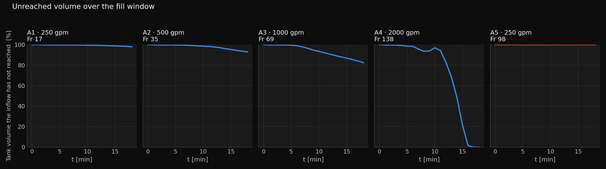
A2 is a fixed nozzle at 500 gpm; A5 is a variable orifice at 250 gpm with the port throttled to a quarter of its area. Their momentum flux is identical by construction, and they land within 1.1% of each other on mixing index, on residual stratification, and on tracer uniformity. A3, meanwhile, has a lower Froude number than A5 and almost three times the mixing. Froude ordering is wrong by about 200%, far outside any numerical doubt here.
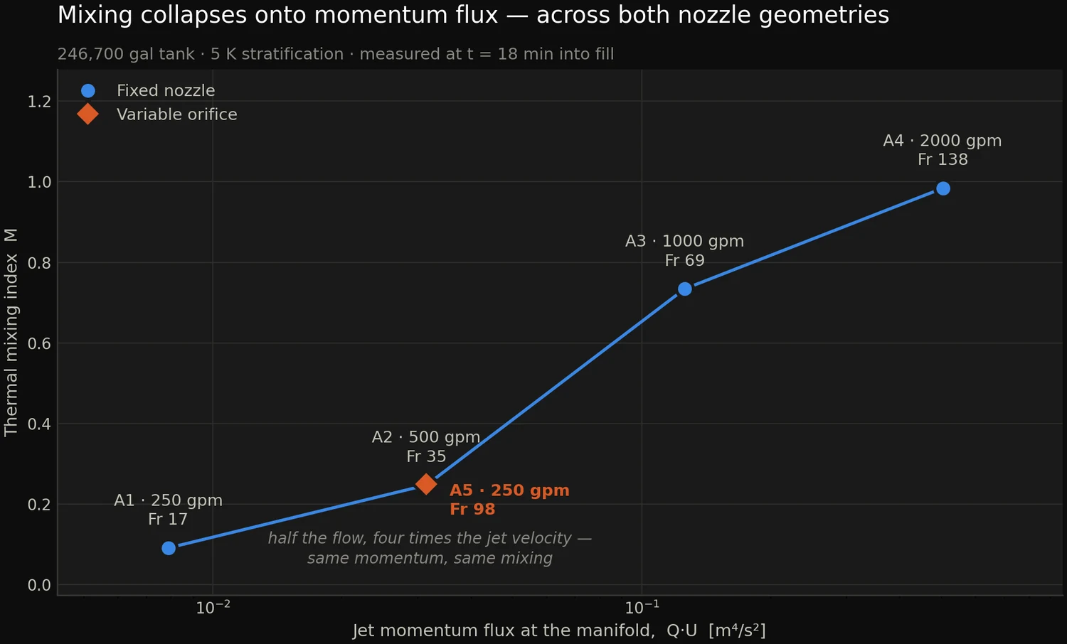
Froude number still does a job: it predicts whether the jet penetrates the thermocline at all. A1 at Fr 17 stalls at 0.57× tank depth, A5 at Fr 98 reaches 1.61×. What it does not set is how fast the tank then turns over. That is two parameters, not one.
THE CONTROLLED COMPARISON
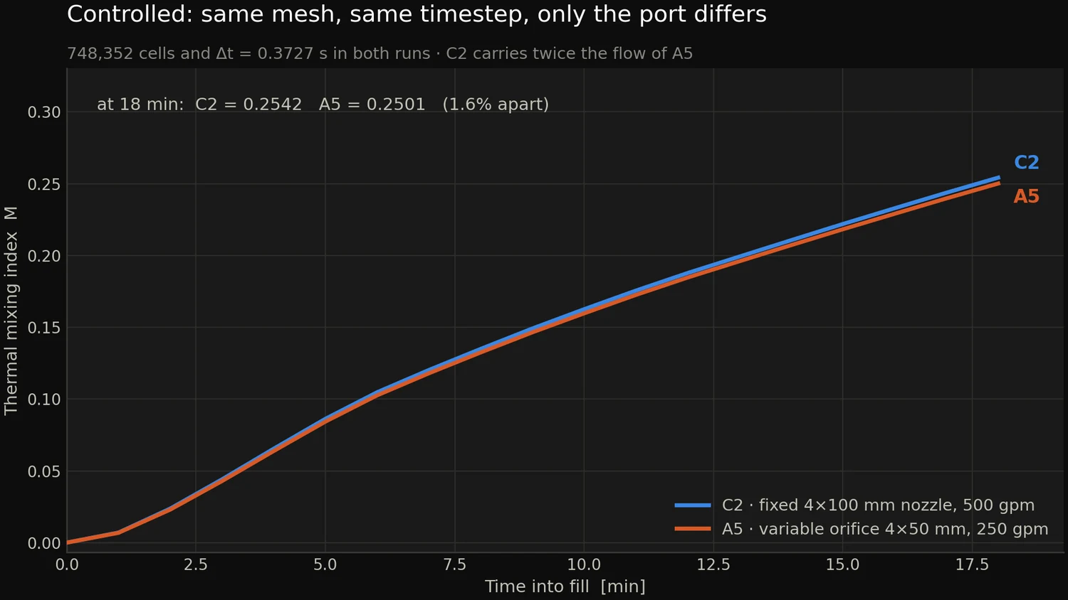
Same mesh, same timestep, only the port differs.
C2 (fixed 4×100 mm port, 500 gpm) against A5 (variable orifice 4×50 mm, 250 gpm) on an identical mesh at an identical 0.3727 s timestep. They finish 1.6% apart on mixing index, 0.2542 against 0.2501, while A5 carries half the flow.
| Case | Inlet | gpm | U · m/s | Fr | Re | z max /H | M @ 18 min |
|---|---|---|---|---|---|---|---|
| A1 | Fixed nozzle | 250 | 0.50 | 17 | 50k | 0.57 | 0.091 |
| A2 | Fixed nozzle | 500 | 1.00 | 35 | 100k | 1.14 | 0.247 |
| A3 | Fixed nozzle | 1000 | 2.00 | 69 | 199k | 2.28 | 0.734 |
| A4 | Fixed nozzle | 2000 | 3.99 | 138 | 399k | 4.56 | 0.984 |
| A5 | Variable orifice | 250 | 2.00 | 98 | 100k | 1.61 | 0.250 |
| C2 | Fixed nozzle | 500 | 1.00 | 35 | 100k | 1.14 | 0.254 |
Every case was generated from one parameter table, and all values are as simulated, computed from the discrete inlet area of the mesh, not from the nominal circle. A3 is both design points: at 1000 gpm the variable orifice is fully open, so fixed and variable are the same simulation. It is run once and reported once.
WHAT THE TANK LOOKS LIKE
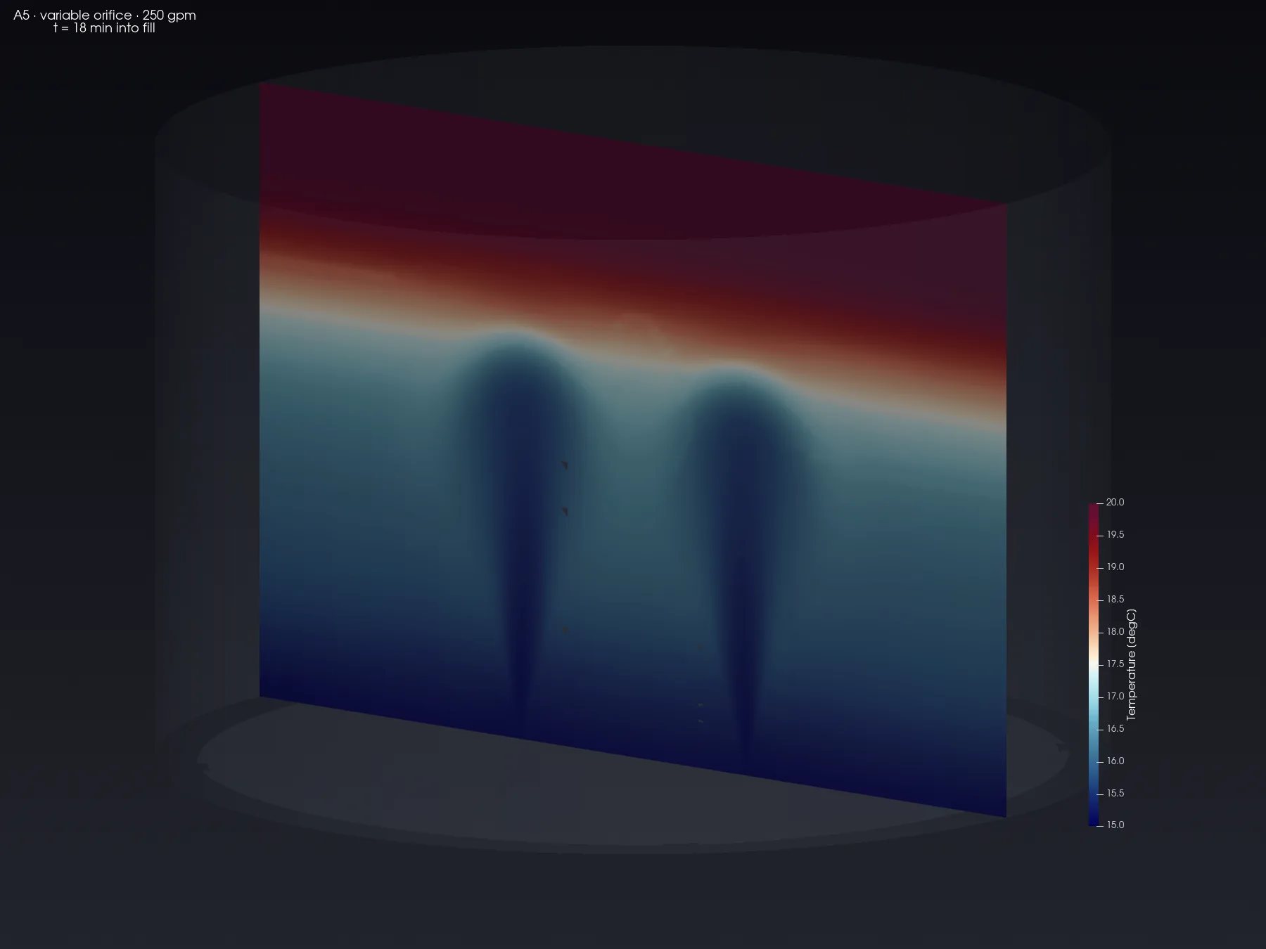
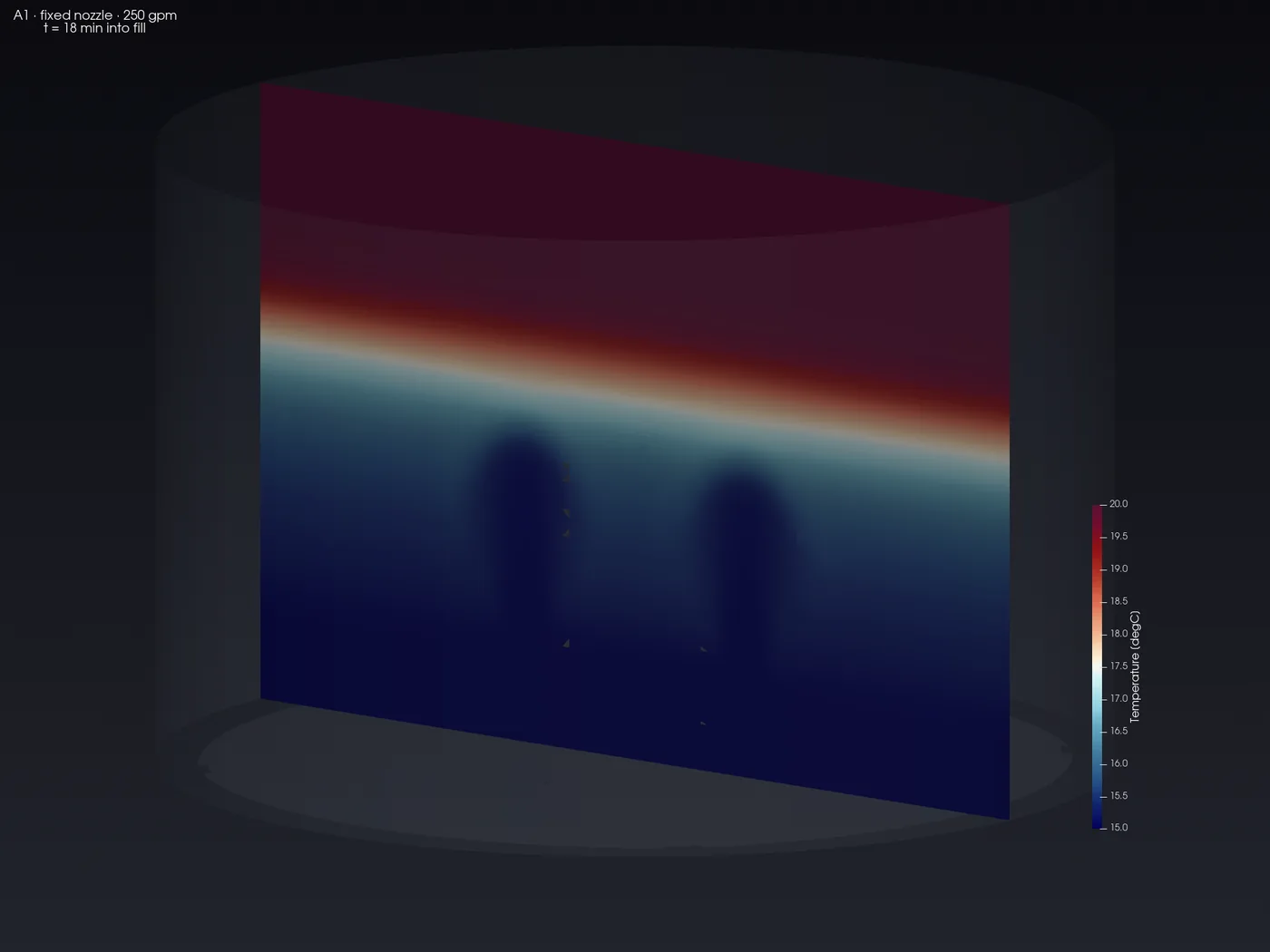
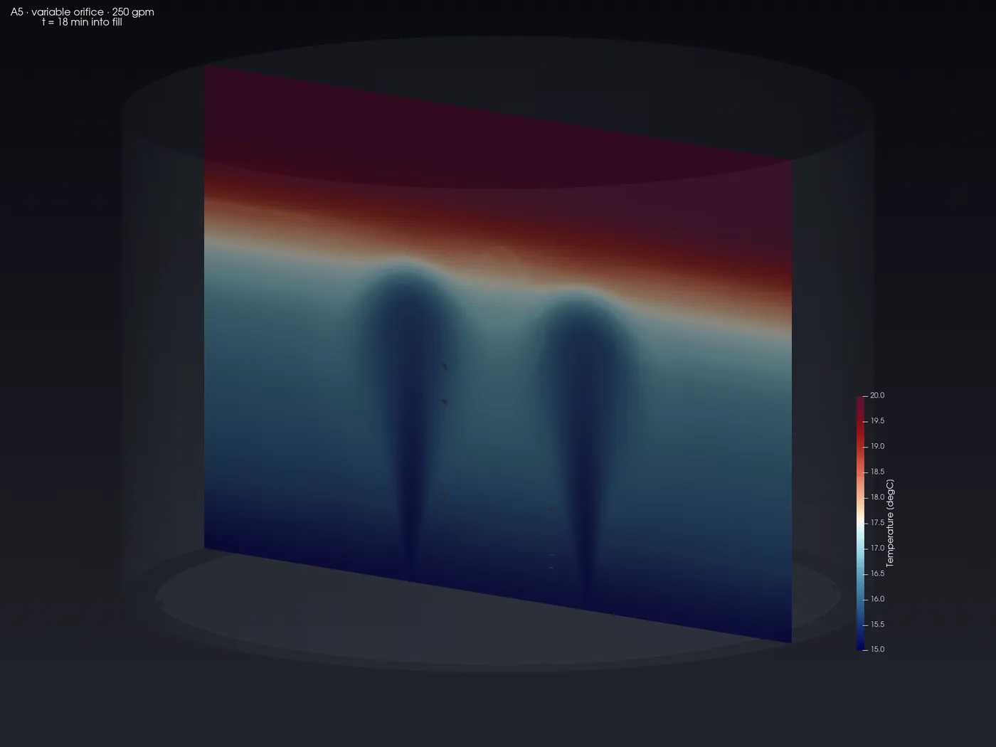
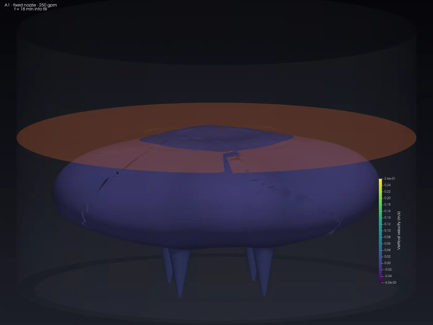
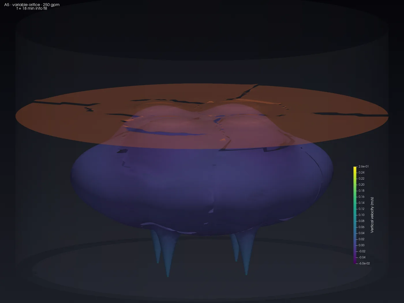
One jet stalls under the thermocline. The other works on it.
Vertical section through two opposed nozzles, coloured by temperature. Cold inflow enters at the floor; the warm stored layer sits above the thermocline at 55% of depth. Both frames are the same 250 gpm.
THE COMMERCIAL ARGUMENT
Q² becomes Q, and that is the whole case for a variable orifice.
For a fixed nozzle, U = Q/A, so momentum flux Q·U scales as Q². Mixing performance therefore falls with the square of turndown. Halve the flow and you lose three quarters of your mixing energy. A variable orifice that throttles area to hold jet velocity makes momentum scale as Q instead: linear, not quadratic. At 8:1 turndown that is an 8× advantage in momentum.
Scaling beyond what was simulated is arithmetic, not simulation, and is flagged as such. The fitted exponent on the unsaturated fixed-nozzle cases is M ∝ (Q·U)⁰·⁷⁵², so an 8× momentum advantage extrapolates to roughly 4.8× the mixing, not 8×. The largest turndown actually simulated is 2:1 in flow at 4:1 in area.
MEASURED HERE, UNDER CONTROL
Throttling to 25% port area at 250 gpm produced mixing indistinguishable from a fixed nozzle at 500 gpm: 0.2501 against 0.2542, a 1.6% difference against a measured numerical uncertainty of 2.7%. Half the flow, the same mixing.
BRING US THE DECISION
Before the inlet manifold is specified.
If a tank has to hold water quality across an 8:1 turndown, the question is what the inlet delivers at the bottom of that range, not at the top. Send us the tank and the duty curve.
OpenFOAM v2412 (ESI), buoyantBoussinesqPimpleFoam, transient, Boussinesq buoyancy, k-ω SST run URANS. Block-structured O-grid, locally refined on the four jet columns; max non-orthogonality 39.9°, max skewness 0.635, volume error −0.03%. Transported scalars: temperature, inlet tracer, water age and chlorine with first-order decay. Full prototype scale, no model scaling. Comparison time 1080 s of tank fill. Basis: a representative tank, not a named client.